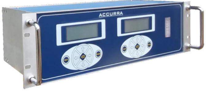
A 4-20 mA output sends the reading as a current, with 4 mA for the bottom of the range and 20 mA for the top; the live zero lets the system detect a broken wire. Relays signal alarms and faults, wired so they fail safe. Modbus RTU sends digital values and status over RS-485. ACCURRA-S offers configurable 4-20 mA, relay alarms and Modbus RTU.
- Convert a 4-20 mA signal to a reading and back
- Explain live zero and fault levels
- Wire relays so they fail safe
- Describe what Modbus RTU adds
4-20 mA
A current loop carries the reading as a current between 4 and 20 mA, which is linear with the configured range. Current does not droop along long cables the way voltage does, so it travels hundreds of metres reliably.
reading = low + (current - 4) / 16 x (high - low)
An oxygen analyser ranged 0 to 25 % outputs 12 mA. The reading is 0 + (12 - 4) / 16 x 25 = 12.5 %.
Live zero. The lowest value is 4 mA, not 0, so a reading of 0 mA means the loop is broken. Many systems treat below about 3.6 mA or above about 21 mA as a fault, in line with the NAMUR recommendation. Configure the control system to alarm on those values rather than treat them as readings.
Relays
A relay output is a dry contact that opens or closes on an alarm: a low alarm, a high alarm, or a fault. ACCURRA-S has relay alarms with configurable set points. Wire them so that loss of power or a wire break puts the system in a safe state, for example normally energised relays that de-energise on alarm. This is called failsafe wiring and is explained further in the glossary: Failsafe relay.
Wiring an alarm contact normally open so that a broken wire looks the same as no alarm. Prefer a circuit where a break signals an alarm.
Modbus RTU
Modbus RTU is a simple serial protocol, usually over a two-wire RS-485 bus, in which a master asks slaves for values held in numbered registers. It lets the control system read the concentration, alarm state, fault codes and diagnostics, and even start a calibration, in digital form without conversion error. Each device has an address; multiple analysers share one bus. Use shielded twisted pair, terminate the bus at both ends and keep to one master.
Which to use
| Need | Output |
|---|---|
| Continuous value to a controller or recorder | 4-20 mA |
| Alarm that trips an interlock or horn | Relay, failsafe |
| Several values, diagnostics, remote calibration | Modbus RTU |
| Redundancy for a critical measurement | 4-20 mA plus relay plus Modbus |
Fault handling matters as much as the reading: decide what each output should do when the analyser is in calibration, warm-up or fault. See Connecting a gas analyser to PLC, DCS and SCADA.
- 4-20 mA carries the reading; 4 mA is the live zero.
- Treat below 3.6 mA or above 21 mA as a fault.
- Relays should fail safe.
- Modbus RTU adds digital values and diagnostics over RS-485.
Check your understanding
Answer in your head or on paper first, then open the answer. Recalling an answer teaches more than rereading.
An analyser ranged 0 to 100 ppm outputs 8 mA. What is the reading?
25 ppm: (8 - 4) / 16 x 100.
Why does a 4-20 mA loop use 4 mA for zero?
So a broken wire (0 mA) can be told apart from a zero reading.
What is failsafe relay wiring?
A circuit where loss of power or a broken wire produces the alarm state, not the healthy state.
Key terms
Frequently asked questions
What is a 4-20 mA signal?
A current that represents the reading, 4 mA at the bottom of the range and 20 mA at the top.
Which outputs does ACCURRA-S have?
Configurable 4-20 mA, relay alarms and Modbus RTU, according to the catalogue.
What is the maximum cable length for 4-20 mA?
Hundreds of metres, limited by the loop's compliance voltage and wire resistance.
Can Modbus start a calibration?
On models that support it; ask for the register map.